

Tools needed:
- ruler
- electric drill and various bits (3/32 in., 7/64 in., 1/8 in., 13/64 in., 9/32 in.)
- small flat screwdriver
- small pliers
- pocket knife or Xacto knife
- crayon or Sharpie
Neaten the parts
- Remove support structures and stray plastic with a blade so parts fit together and bolt holes are clear (this may have been done already).
- Oval windows in the camera tray walls will have support structures which can be removed.
- Cut off the small square tabs near the end of each arm of the upper frame.
- The cylindrical top bracket on the upper frame will have support structures to remove. The cylinder can be drilled with a 9/32 in. drill bit (but don’t enlarge the hole).
Attach leg brackets to upper frame
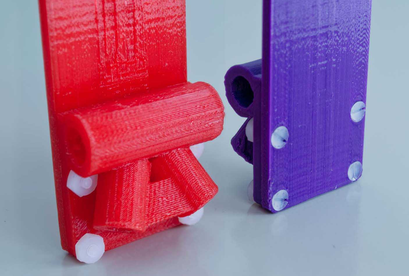
- Legs or bumpers can be attached directly to the dual camera tray, so these leg brackets on the upper frame are optional.
- Fasten four nylon screws and bolts as shown. Tighten firmly, but take care not to strip the nylon threads.
- The uppermost nuts can be a tight fit, and it might help to cut a bit off two of the nut’s corners with a sharp blade.
Drill camera platforms for tripod screws
The goal is to fasten the cameras to the platforms with their backs snug along the platform’s lip and their centers of mass centered along the long axis of the platform. Almost every camera will require a hole drilled in a different location. If you plan to operate the cameras via USB, check that the mounting arrangement will accommodate USB plugs. Materials: camera tray, tripod thumb screws, cameras.
- Mark the lengthwise position of the hole for the tripod screw.
- Lay each camera (with batteries inserted) on its back on a pencil or crayon to determine its center of mass along its long axis. Mark the center on the back of the camera (e.g., with a crayon).
- Mark the position of the tripod socket on the back of the camera (e.g., with crayon).
- Measure and mark the center of each camera platform’s long axis (e.g., with crayon).
- Align a camera on the platform so its center of mass is at the center of the platform’s long axis, and mark on the platform the lengthwise location of the tripod socket.
- Mark the front-back position of the hole for the tripod screw.
The larger yellow thumb screw is for the lower camera. The platform lip leaves less room under the central platform where the smaller red thumb screw is. - Measure the distance from the center of the camera’s tripod socket to the back of the camera body. If the lower part of the camera is rounded, measure to the place the camera touches the platform lip when in position.
- Measure on the top of the camera platform this distance (1) from the inside of the lip to where the center of the tripod hole should be. Mark the spot on the platform where the lengthwise and front-back position of the tripod socket meet. Mark it with a large plus so it remains visible after drilling starts. Precision is required, so scratching a plus with a sharp blade works well.
- Scratch a lead hole with a knife to get the drill bit started.
- Drill the holes for the tripod thumb screws.
- The center platform is much harder to drill because it must be addressed at an angle. Deal with it.
- Drill a hole with a small bit (~1/8 in.). The plastic has a low melting point and will quickly soften during high speed drilling. Drill carefully because the bit will start to “swim” through the plastic when it gets warm.
- Enlarge the hole with the 1/8 in. bit and cut away any melted plastic. Place the camera in position on the platform and look through the new hole into the tripod socket. If it looks like it is close, proceed.
- Enlarge the hole with a 13/64 in. bit. Clean up the hole and check again that it is properly aligned by sighting through it from the bottom into the camera’s tripod socket.
- Enlarge the hole until it is almost 1/4 in. diameter. The plastic is soft enough that this can be done with the 13/64 in. bit and you can carve the hole closer or farther from the lip so the camera will be snug against the lip when it is screwed on.
- Try to insert the tripod thumb screw into the hole. The thumb screw must turn freely in the hole before you try to thread it into the camera or you risk stripping the threads in the camera’s tripod socket. Ideally, the screw will thread itself through the plastic, but then turn freely when it is all the way in. This will strip the threads you just made in the plastic, but the screw will stay inserted in the platform when the camera is not attached, which is convenient. If the hole gets too big for this, that’s okay.
- If the camera mounts too far from the lip, enlarge the hole so the camera can be screwed on snug against the lip. This is important so that both cameras are pointed in the same direction whenever they are mounted and capture the same scene (e.g., for VIS/NIR pairs). It is also important so the cameras cannot rotate and begin to loosen the thumb screws (bad thing for flying cameras, but the camera’s wrist strap or other lanyard should always be looped around the rig for safety).
- If the hole gets too big to hold the thumb screw, you can make the hole smaller by melting some PLA with a soldering iron and adding material to the inside of the hole. If you find a random piece of plastic with your rig parts, use that.

Attach camera tray to upper frame
Bolt holes are present in both the camera tray and upper frame and these work for most camera pairs. Skip to step 3 below to use the existing holes. If your cameras are not balanced using the existing holes, follow the instructions in steps 1 and/or 2 below to drill new holes.
With both cameras mounted on the tray, the center of mass will no longer be the center of the tray. The upper frame must be attached at the new center of mass.
- Drill holes on either side of the camera tray.
- With batteries in the mounted cameras, lay the tray upside down on a pencil or rod to find its center of mass between the two cameras. Mark that place on both sides of the tray.
- Determine the location of the hole through the side wall of the tray for the bolt to attach the upper frame. At the marked center of mass, measure 11 mm down from the top of the tray (flat side). This spot should be between the center camera platform and a small oval window (there is a pad of solid plastic embedded in the wall there). Mark the drill hole on both sides of the tray the same distance from the oval window. Make a large plus mark on the outer side of the tray wall so that it remains visible after drilling begins. Scratch an indentation to get the drill bit started.
- With the cameras removed, drill a lead hole with a small bit (e.g., 3/32 in.). Be prepared for the bit to swim through soft plastic.
- Enlarge the hole with a 1/8 in. bit. Clean away the excess plastic and see if the 3/4 in. thumb screw passes through easily. It should turn freely.
- Drill holes on either side of the upper frame.

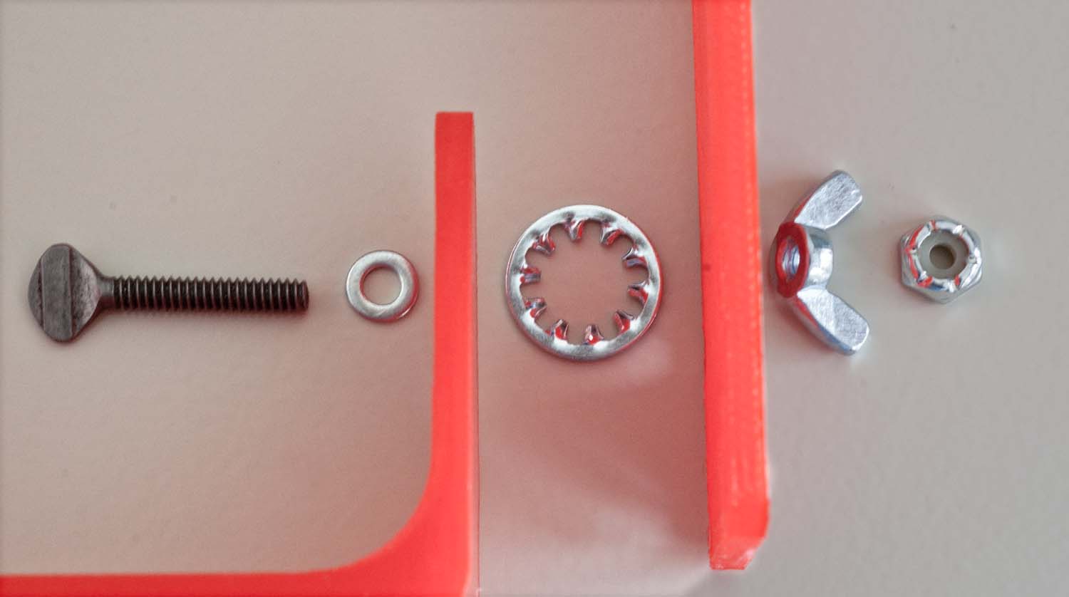
The large toothed lock washer goes between the camera tray and the upper frame. The wing nut and lock nut go on the outside of the frame. - The matching holes through the upper frame should be in the center of the frame (front to back) and about 12 mm above the top of the leg brackets (just high enough so the wingnut can turn) . Mark this spot on the outside of the frame and drill as above. Make sure the height is exactly the same on both arms of the frame. The thumb screw should pass through easily.
- Attach the hardware as shown. The nylon insert lock nut should be threaded onto the end of the thumb screw just far enough so the screw end is flush with the outside of the nut. It ensures that the wing nut cannot come off.
- When assembled correctly with the large lock washer between the upper frame and tray, the wing nut can be tightened by hand so that the weight of the cameras will not change the angle of the camera tray. Do not try to rotate the tray when the wing nut is tight, loosen it first.
Configuring legs and bumpers
There are 12 brackets for holding legs or bumpers, making many configurations possible with the included tubing. However, to save weight, no legs, leg brackets, or bumpers are necessary.

- Use a blade to clean the inside edges of the ends of the bracket tubes.
- Cut polyethylene tubing to the correct lengths for bumpers and legs (see parts list). A sharp Xacto knife works well. There are two sizes of tubing — the thicker one (3/8 in.) is only for leg loops at the lower end of the upper frame.
- The angled brackets on the upper frame are smaller (1/4 in.) than the others. Insert short (3 cm) pieces of 1/4 in. oak dowel to attach the larger size polyethylene tubing. Use pliers to twist the dowels into the brackets.
- If the dowels are too tight the brackets can be reamed with a 1/4 in. drill. Use caution if drilling the leg bracket — a drill bit can pull itself in quickly. If the dowels fit loosely, they could fall out in flight — go to plan B (currently not defined, so don’t enlarge the brackets too much).
- For all other brackets, 5/16 in. tubing can be attached as legs or bumper loops. The tubing loops are better for balloon photography because they avoid hooking the vertical balloon line better than straight legs.
- The 5/16 in. tubing should slide through the horizontal plastic tubes with concerted effort. If the fit is too tight, use a 9/32 in. bit to ream the holes a bit. It is good to have a tight fit.
- For oblique photography, the upper horizontal bumper might prevent the tray from tilting. Therefore it is convenient to make that bumper from two pieces of tubing so half of it can be removed to allow the tray to tilt.
- Where the ends of a loop of tubing meet inside a horizontal plastic tube, insert a 1 inch (2.5 cm) piece of white plastic (acetal) rod in the ends to join the tubing more securely.
Attaching the rig to a suspension system

The shaft for a Picavet or pendulum suspension can be inserted into the vertical, cylindrical bracket at the top of the Titan 2 Rig frame. A single hole through the side of the bracket is for a cotter pin.
- Use a 7/64 in. drill bit to enlarge the hole on the side of the cylindrical bracket. The alignment is important so the cotter pin can pass through the hole in the inserted shaft.
- If the shaft from the suspension is too tight, smooth the upper and lower ends of the bracket tube with a blade or ream the hole with a 9/32 in. drill bit.
- Insert the carbon shaft so one of the holes through it is below the frame and the other hole aligns with the hole through the cylindrical bracket.
- Insert a cotter pin through the bracket and the shaft.
- Always insert a second cotter pin below the frame.
Connecting electronics
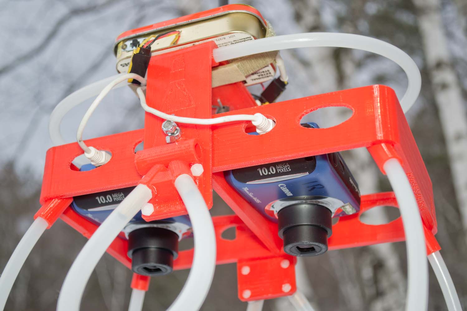
- External electronics for triggering camera shutters simultaneously can be mounted on the shoulders of the upper frame. USB cables can reach the cameras through the oval holes in the sidewalls of the tray. If the alignment is not right, the oval windows can be enlarged. For some cameras, cables with right angle USB connectors are more convenient.
Safe flying
- Always secure the cameras to the Titan 2 Rig with a lanyard. The wrist straps on point & shoot cameras work well for this.